Raspberry Pi is a small single board computer, yet very powerful and that is exactly why people use it so much. Usually it is used for controlling some GPIOs to turn ON/OFF some light, to read a temperature sensors, smart homes, even in industry. Often there is a need to control devices with higher voltage and a big power consumption. such that it can not be controlled directly from the Raspberry Pi it self. In those cases, relays can be used and a Raspberry Pi is perfect for controlling this. With use of a relay you can can control totally independent device with high loads. Raspberry Pi relay control, enables you will be able to control big (and small) loads.
In real world scenario there is usually not just one such device that needs to be controlled with a relay but there are many in one common area of the application. Raspberry Pi does have some GPIOs for controlling multiple relay, but when they are used for controlling relays, they can’t be used for other functionalities. For that you want to use an expansion board and here you’ll learn how to connect and control a PoRelay8 board.
PoRelay8 board from PoLabs d.o.o. is a module with 8 independent relays which can be controlled via I2C or even CAN bus! What even better, it can be connected in series which enables you to extend number of relay outputs from 8 to 80. That’s a lot of outputs, right? To control a PoRelay8 board, other embedded controllers such as PoKeys57CNC and similar (which has I2C bus) can be used.
Wait a minute, am I getting this right? Up to 80 independent relay outputs with just 2 used GPIOs on the Raspberry Pi?? Yes, you are totally right! So let’s begin with the setup.
What will you need to begin?
Raspberry Pi board
PoRelay8 expansion module
Power supply for the Raspberry Pi (micro-USB or USB-C type, depends on which Pi board you have)
12V power supply for PoRelay8 module
microSD card (at least 16GB)
A keyboard and a mouse
mini HDMI cable for your screen
Internet connection (WiFi of Ethernet)
Some cables for connection between Pi and PoRelay8
Set up the microSD card for the Raspberry Pi – Raspberry Pi OS
You may skip this step, if you have already done it and you have a working Raspberry Pi (Continue reading on the “PoRelay8 module” section). For all of you who doesn’t have it done yet, follow me. Using the Raspberry Pi Imager is the easiest way to install Raspberry Pi OS on your microSD card.
Click on the link for the Raspberry Pi Imager that matches your operating system.
When the download finishes, click it to launch the installer.
2. Using the Raspberry Pi Imager
Anything that’s stored on the microSD card will be overwritten during formatting. If your microSD card currently has any files on it, e.g. from an older version of Raspberry Pi OS, you may wish to back up these files first to prevent you from permanently losing them.
When you launch the installer, your operating system may try to block you from running it. For example, on Windows I receive the following message:
If this pops up, click on More info and then Run anyway. Follow the instructions to install and run the Raspberry Pi Imager. Then insert your microSD card into the computer or laptop microSD card slot. In the Raspberry Pi Imager, select the OS that you want to install and the microSD card you would like to install it on.
Note: You will need to be connected to the internet the first time for the the Raspberry Pi Imager to download the OS that you choose. That OS will then be stored for future offline use. Being online for later uses means that the Raspberry Pi imager will always give you the latest version.
Then simply click the WRITE button and wait for the Raspberry Pi Imager to finish writing. Once you get the following message, you can eject your SD card.
4. Connect your Raspberry Pi
Now get everything connected to your Raspberry Pi. It’s important to do this in the right order, so that all your components are safe. First insert your microSD card you’ve set up with Raspberry Pi OS into the microSD card slot on the underside of your Raspberry Pi.
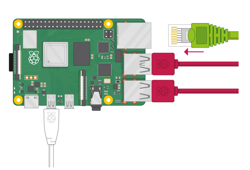
Now connect a keyboard and a mouse in the USB ports on Raspberry Pi (it doesn’t matter which port you use).
Now connect your screen.
Raspberry Pi 4
If you have the Raspberry Pi 4, you’ll notice that it has two mini HDMI ports. Connect your mini HDMI cable to the HDMI0 port (nearest the power in port).
Raspberry Pi 1, 2, 3
Your Raspberry Pi has only one HDMI port.
Since your Raspberry Pi isn’t powered yet, you shouldn’t see anything on the screen. We’ll need an internet connection later so in case you don’t have a WiFi to connect to, let’s plug-in the Ethernet cable.
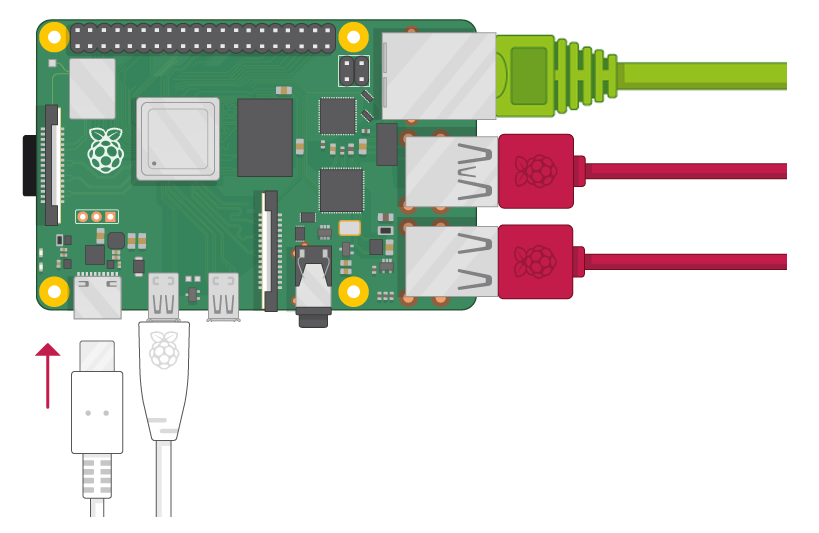
5. Start up your Raspberry Pi
Your Raspberry Pi doesn’t have a power switch. As soon as you connect it to a power outlet, it will turn on. Plug the power supply into a socket and connect it to your Raspberry Pi’s power port.
You should see a red LED light up on the Raspberry Pi, which indicates that Raspberry Pi is connected to power. As it starts up (this is also called booting), you will see raspberries appear in the top left-hand corner of your screen. After a few seconds the Raspberry Pi OS desktop will appear.
First start up procedure
When you start your Raspberry Pi for the first time, the Welcome to Raspberry Pi application will pop up and guide you through the initial setup. Click on Next to start the setup and insert your time, date, timezone, login password, etc. When all is set and done, restart your Pi.
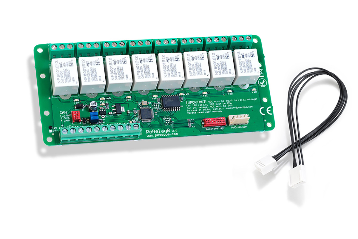
PoRelay8 module
Now let’s put hands on the PoRelay8 relay board. Board has many connectors, but let’s focus on what you’ll need today.
Connect PoRelay8 with Raspberry Pi
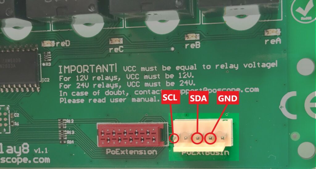
You’ll be using the PoExtBus in connector. It has the I2C bus connections that you need.
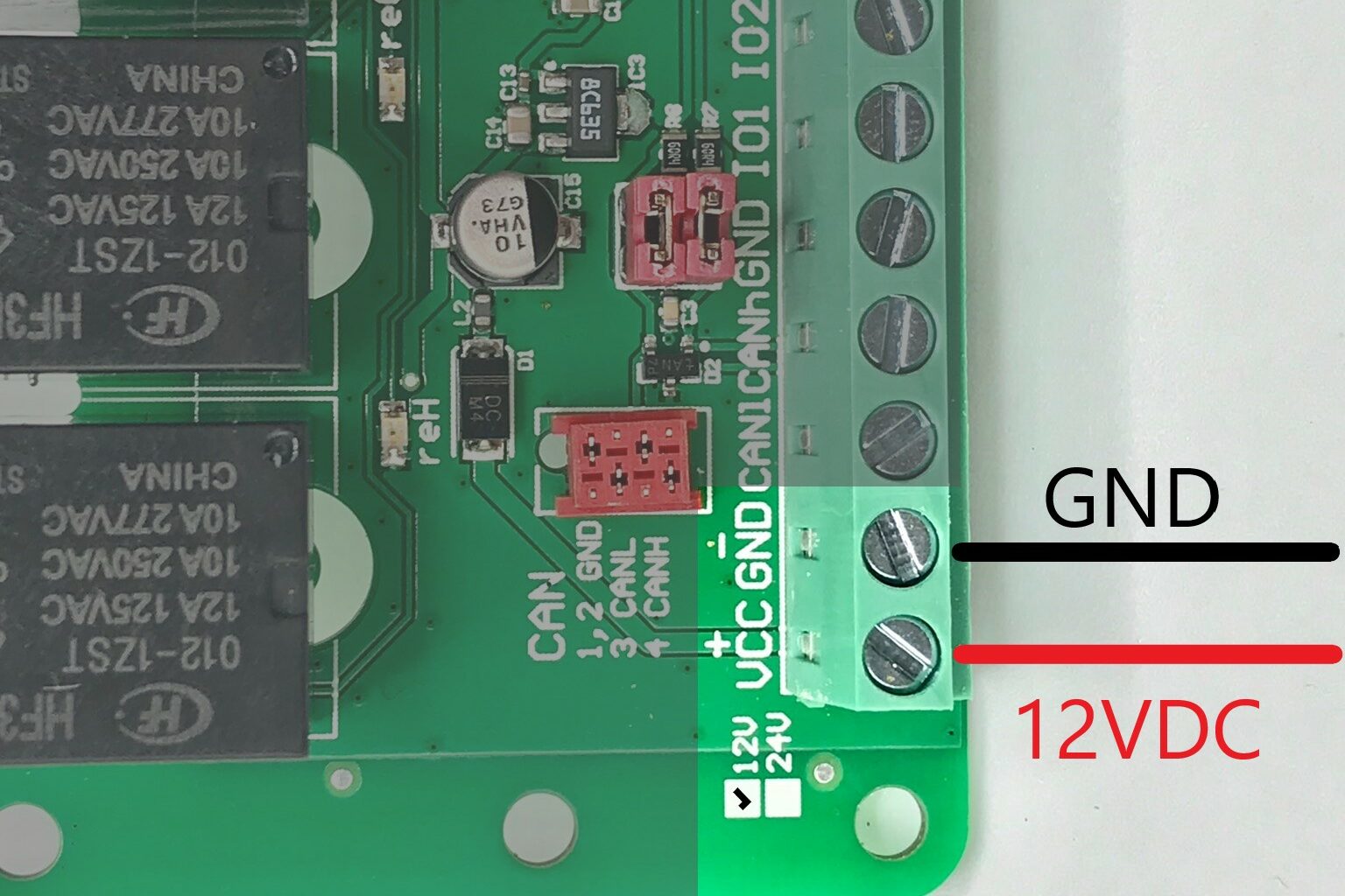
PoRelay8 block needs a separated power supply to control relays. Connect a 12V power supply to the power supply connector as it is shown on the next image.
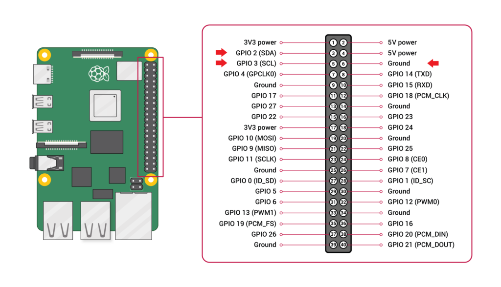
You are now ready to connect a PoRelay8 with the Raspberry Pi. To do that, let’s check the Raspberry Pi GPIO pinout.
Now connect the same-named connections. So SDA pin from PoRelay8 module goes to SDA pin on the Raspberry Pi, etc.
Enable I2C on Raspberry Pi
Now when the initial set up of your Raspberry Pi is done and everything is connected, you’re ready to proceed with the work. Raspberry Pi will control the PoRelay8 board via an I2C bus. The main benefit of this bus is that it uses only two hardware connections (SCL and SDA) in order to control many different devices – in this case it will control 8 relays. I2C bus on a Raspberry Pi is by default disabled! To enable it, open a terminal and type in:
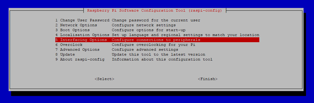
sudo raspi-config
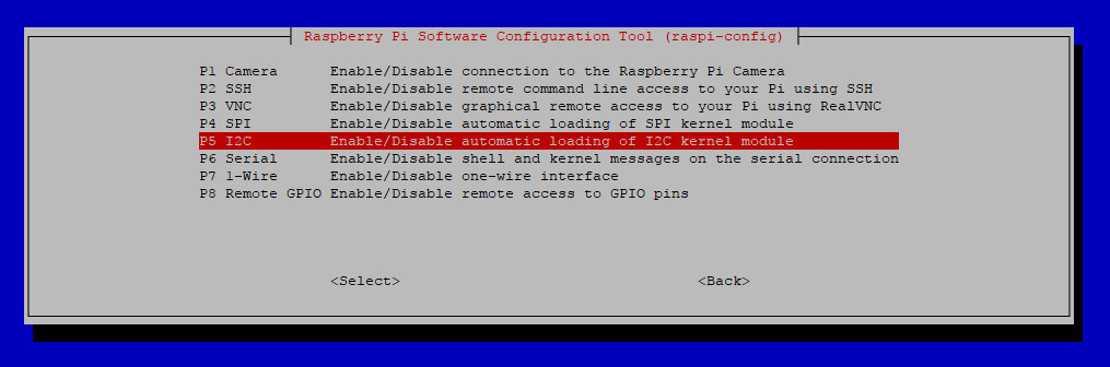
A configuration tool will open. With use of up and down keys select the “Interfaceing Options” then hit Enter. A new screen will appear, select “I2C” and hit Enter again. You’ll be asked, if you want to enable the I2C bus, select yes and Enter.
Now restart the Pi.
sudo reboot
Discover I2C devices
After reboot, I2C should be enabled. Each device on the I2C bus mus have a unique address which is later used to invoke a specific device (for read and write operations). This address is usually a 7-bit number but also 10-bit address exists. To find out which devices are connected to your I2C bus, open a terminal and type in:
sudo i2cdetect -a -y 1
i2cdetect – is a command which accepts some parameters.
-a – is a parameter that tells the command to scan over all possible addresses.
-y 1 – is a parameter that tells the command to select the I2C bus 1. Raspberry Pi 4 has actually 4 I2C buses but you’ll be using bus 1.
Next what you’ll see is hopefully something like that:
i2cdetect tries to contact every possible address and if device is present, it should reply when its address is called. As we can see, our PoRelay8 board has address 0x7b. If you can’t see any connected device, please check if the PoRelay8 is powered with a 12V and if the connections are properly connected…
Pigpio library
A pigpio library is used for communication over i2c protocol. It provides nice Python module for communication with pigpio daemon. Python commands reference can be found on library website. Here are short instructions how to install pigpio library (If you already have installed the pigpio library, just skip to the next section, otherwise follow the procedure):
wget https://github.com/joan2937/pigpio/archive/master.zip
unzip master.zip
cd pigpio-master
make
sudo make install
If you encountered any problems, please refer to the official pigpio library page.
After installation start pigpio daemon manually with command:
sudo pigpiod
If you wish to start the deamon at boot time, add this command into /etc/rc.local file.
Raspberry Pi relay Control with Python – example 1
Now as you know that the PoRelay8 board address and pigpio daemon is running you can use python script to send commands to our relay board as is presented in the following example.
To control PoRelay8 board outputs, 3 bytes of data must be sent to board.
1st byte is command, which tells PoRelay8 board to turn on or off the outputs.
2nd byte is actual setting of the outputs, where every bit corresponds to one relay output.
3rd byte is sum of first and second byte.
Now open a Mu editor from Raspberry Pi Icon → Programming → Mu and copy-paste example code, then hit run.
import pigpio

# Set PoRelay8 board i2c address
DEVICE_ADDRESS = 0x7b

# Connect to Rapberry Pi and open i2c handle to bus 1
pi = pigpio.pi()
bus1 = pi.i2c_open(1, DEVICE_ADDRESS)

# Set PoRelay outputs
command = 0x20
outputs = 0x55
checksum = (command + outputs) & 0xFF

request = [ command, outputs, checksum ]

# Send to PoRelay8
board pi.i2c_write_device(bus1, request)

# Close bus1 handle
pi.i2c_close(bus1)
Relays A, C, E, G should turn ON.
Raspberry Pi relay Control with Python – example 2
import pigpio
import time

# Set PoRelay8 outputs
def i2c_set_outputs( outputs ):

    # Set Porelay outputs
    command = 0x20
    checksum = (command + outputs) & 0xFF

    request = [ command, outputs, checksum ]
    pi.i2c_write_device(bus1, request)

    return

# Set PoRelay8 board i2c address
DEVICE_ADDRESS = 0x7b

# Connect to Raspberry Pi and open i2c handle to bus 1
pi = pigpio.pi()
bus1 = pi.i2c_open(1, DEVICE_ADDRESS)

# Initial output value
output = 0x01

while 1:
    i2c_set_outputs(output)

    # Rotate output
    if ( output < 0x80 ):
        output <<= 1
    else:
        output = 0x01

    # Wait for 200 ms
    time.sleep(0.200)

# Close bus1 handle
pi.i2c_close(bus1)